Compressor modelling
A compressor model describes what happens to a fluid going through a compressor and calculates how much power is required in the process.
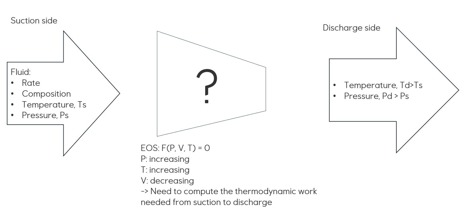
At the suction side, one need information about the fluid (natural gas) which has a (static) specification of the
composition, a specified rate, a temperature and a pressure. As the fluid is going through the compressor in a fluid
dynamic process, the enthalpy changes, resulting in a new state and both the pressure and the
temperature of the fluid is increased, while the volume is decreased. This change is calculated using an
equation-of-state (EOS) model. See Fluid model

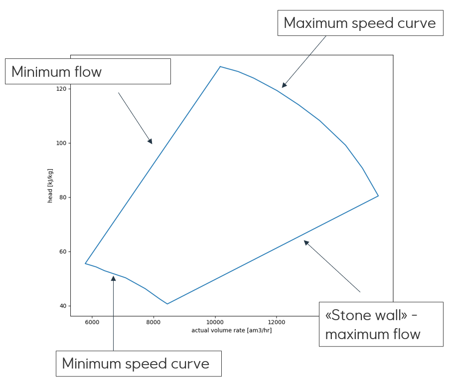
eCalc does not perform fluid dynamic modeling. Instead, the behaviour of the compressor is described by a polytropic compressor chart which specifies both the operational domain of the compressor, but also relates volume rate, head and efficiency for the compressor.
An isentropic (adiabatic) compression is the process where no heat is added or removed from a system. In a polytropic process, changes in the gas characteristics is considered. Dynamic natural gas compressors typically follow a polytropic process defined by the formula , where is the polytropic exponent which is experimentally determined for a given compressor.
 The power need for compression is given by
and the relationship between polytropic head and the pressures are
where is the polytropic exponent, the compressibility, is the gas constant, is the inlet temperature and the molecular weight.
Further, the polytropic exponent is approximated as
where is the heat capacity ratio of the fluid.
and are not for inlet conditions, but average values for the fluid throughout the process, and the polytropic process and the calculations are iterated until these converge.
If there is only one compressor, the outlet pressure for each compressor is known, and the polytropic head and efficiency may be calculated from directly from the above polytropic head and efficiency formulas.
However, for compressor trains, the intermediate pressures are not known ahead, instead one may use the fact that all compressors run with the same speed as they are mounted on the same shaft.
To calculate the energy usage for the compressor train using the common speed, eCalc uses a forward model to
calculate the outlet stream given the inlet stream and a given speed. Then, this model is iterated until the discharge pressure is equal to the requested discharge pressure for evaluation. To use this model, see
Variable speed compressor train model An alternative is to neglect the common speed property of the train, an instead assume (incorrectly but maybe good
enough for some purposes) that the pressure fraction is equal for all stages. With this assumption, the intermediate pressures can be calculated and each stage may be calculated independently without the speed iteration. To use this model, see
Simplified variable speed compressor train model.
In some cases, the shaft of the compressor train can only run on a single fixed speed. In these cases eCalc needs
information about how the pressure should be controlled to meet the required discharge pressure. Available pressure
control options are choking and recirculating using anti-surge valves. To use this model, see Single speed compressor train model.
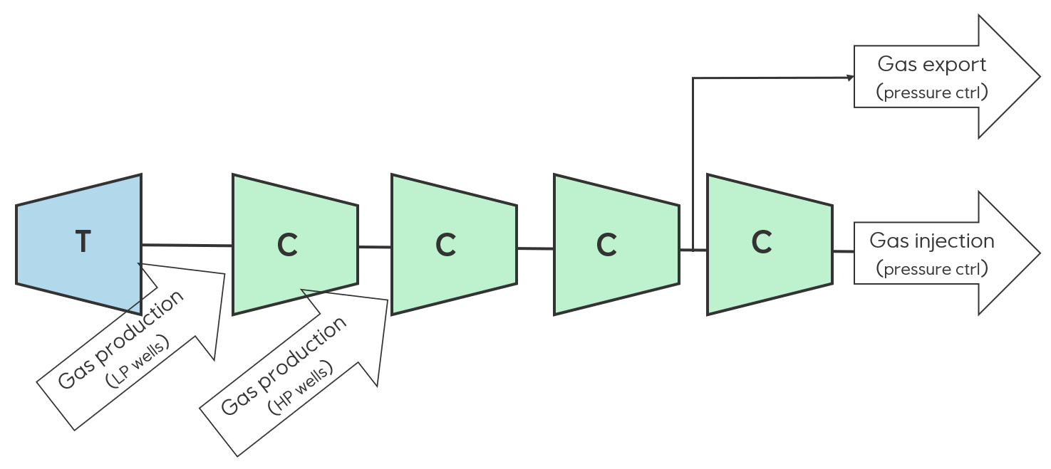
In other cases, the compressor trains have more complex setup and process control which needs a more flexible model. The
figure below shows an example where one may have two inlet streams with different pressures and potentially different
gas compositions and one outlet stream for export gas with a pressure control. To use a model suitable for such cases,
see Variable speed compressor train model with multiple streams and pressures.
